text and photos by Tom Troughton
 For me, the hardest part of this article was making an effort to sit in front of the blank computer screen and starting. Venita Lake had been gently nudging me to write it ever since we met during the layout tours associated with the 1995 Gateway Division fall meet. Venita, her husband Richard, Bob Amsler, Steve Rosnick, Richard Schumacher and myself were riding together visiting the St. Louis layouts when I mentioned some of the techniques our club used when it made its new HO modular layout. She suggested I write it up for publication in the RPO. Two years later, here it is.
I belong to the Capital City Model Railroaders, a group of modelers in Jefferson City that’s been in existence for more than twenty years. Prior to our modular efforts, the group was an informal gathering of individuals who met each Monday night at the home of D.L. Eichelberger, a long time NMRA member, MCoR Director and organizer of the group. “Eich” is gone now, but the group remains.
We decided to construct a modular layout in the late 70s when module type layouts were just beginning to hit the scene. Our standards were loosely based on the “N-Track” theme, but enlarged for HO.
We use two by four foot modules with a three track main line with 4½” setbacks from each end. Legs were 2″x2″ boards cut from 2″x4″s. Six-pin Jones Cinch connectors joined the under table wiring busses and a section of nine inch snap track was dropped into place between each module.
It was a pretty common arrangement, and the group displayed the setup at various meets and events around the Mid-Missouri area. We did, however, have a few problems. The 2″x2″ legs were never straight and the 9″ sections of track never seemed to fit. They were always too long or too short. Each time we set up we were cutting new sections of flex track.
Around the mid to late ’80s we retired the modules. The club’s railroading efforts didn’t stop however. We continued to meet Monday evenings in Round-Robin style in each other’s homes and work on the host’s layout, talk trains or watch railroad videos.
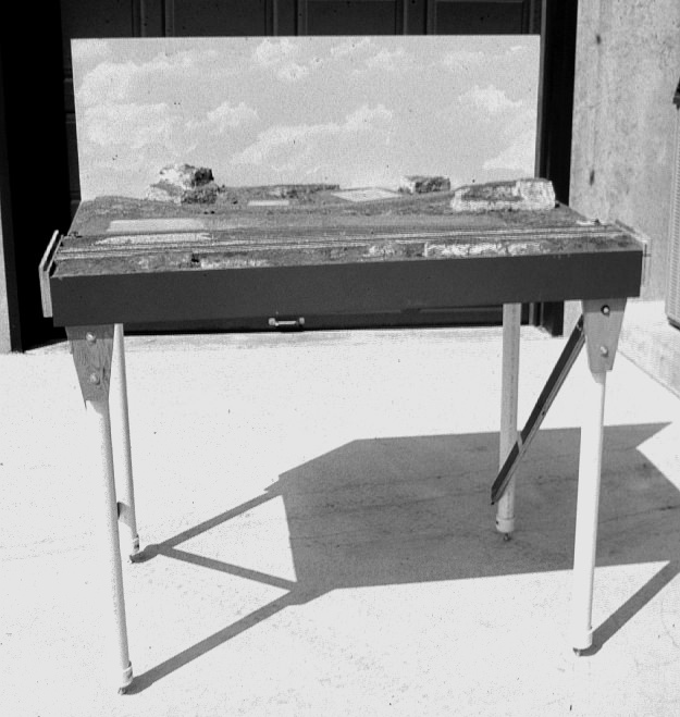
About three years ago, we decided to once again build a modular layout system. The mistakes of the past were reviewed and a new set of construction standards proposed. The new modules would be 30″ deep by four feet long. Rails would run to the end of each module and be protected by end boards.
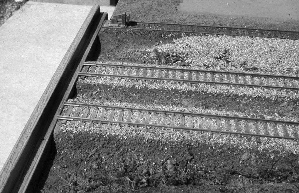
End of typical HO module.
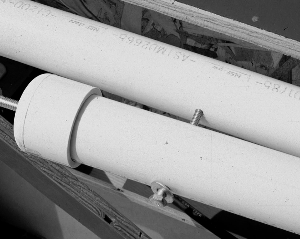
Our mainline would consist of two tracks, on 2½” centers with a #6 turnout being the minimum allowed from the main line. The legs would be 1½” PVC pipe with 3/8″ carriage bolts for height adjustment in their base.
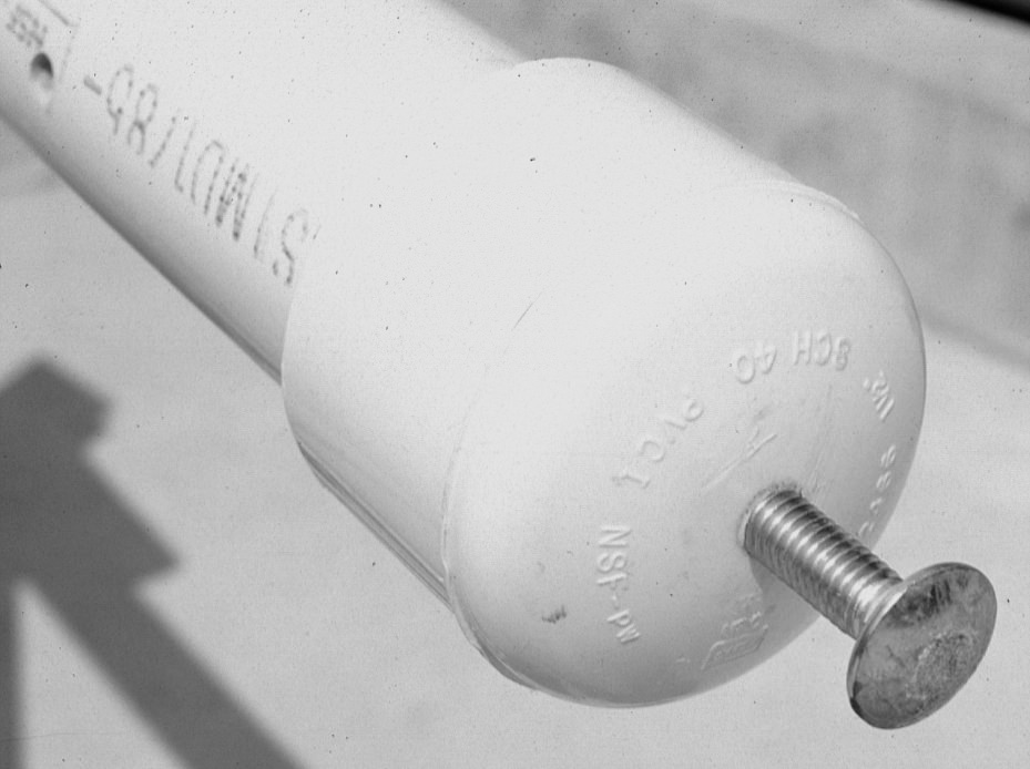
PVC pipe leg with leveling adjustment bolt.
We ran six #16 multi-colored stranded wires below the tracks and connected them to 6-pin Cinch Jones connectors; male connectors on the right side and female sockets on the left. Four of the wires are used for train control while the other two are for future use, possibly phone communications.
We also included a 110 VAC circuit using #14 gauge flexible wire with a duplex receptacle on the left underside end and a grounded plug at the right. We checked each module with a polarity tester to be sure the wiring was correct.
The basic modules were built from ¾” birch veneer plywood. We could have used a lesser quality wood, but the veneer plywood was straighter and easier to work with. The club met at my workshop for a couple of evenings in a row where we ripped the plywood sheets into properly sized components. The PVC pipe was cut to length, and with the help of drilling jigs, holes were drilled for mounting
them to the modules.
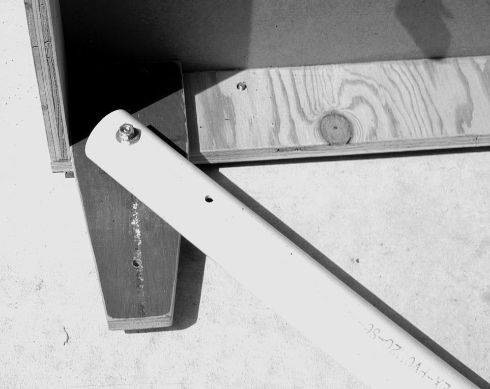
We made 10 inch long leg mounting extensions from the ¾” plywood to serve as swivel points for the PVC legs. These extensions allow us to set the modules on the ground without worrying about snagging the wiring on something. They also make it easier to grab onto the ends when carrying them to and from the display site.
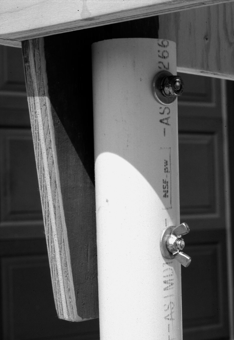
Mounting of the PVC leg to the HO module.
Quarter inch machine screws, washers, lock-nuts and wing-nuts secure the legs to the plywood extensions. Each leg pair is strengthened with a one inch wide piece of ¾” plywood attached diagonally, adding stability to the module. The plywood strips were attached with inch and a half machine screws. The nice thing about working with PVC pipe is it can easily be drilled and tapped to accept the bolts.
This hinged leg arrangement makes transporting the modules much easier than our previous units. We were always misplacing the legs or wondering how to keep them with their respective units. The legs never come off these new modules. We merely loosen the wing-nuts, remove the bolts and swing the legs into their closed position. Near a spot where the legs touch in this folded position, we drilled clearance holes in one leg and tapped the other to accept one of the machine bolts removed earlier. That way they’re secured to one another.
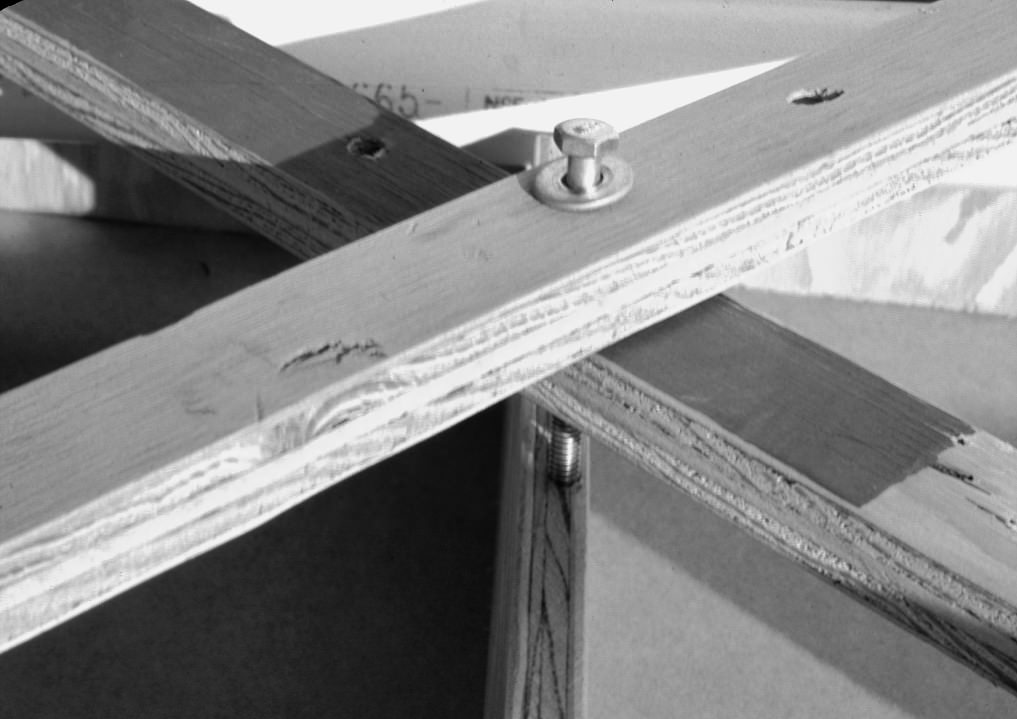
Demonstration of the hinged PVC pipe leg.
The two diagonal running boards were also drilled with clearance holes, letting us fasten them together with one of the wing-nuts and bolts removed from one of the legs.
The PVC pipe legs fold together for transportation.
To add strength, yet retain a light-weight module, we ran another piece of plywood lengthwise and attached a piece of ½” thick by 12″ wide Blandex as the subroadbed. The front and end boards of the module frame were mitered so the subroadbed could be glued in place. When the roadbed was added, the track would be above the local terrain, creating a raised roadbed effect. In later modules, we replaced the Blandex with ½” thick by 12″ wide Celotex house siding.
Plywood cross-supports are used.
Homosote, 4′ long and only as wide as the two track mainline was glued to this subroadbed. To be sure the Homosote came exactly to the ends of the modules, we made a random crosscut in it on my bandsaw and slid the square ends out towards the edges. The gap made by the bandsaw was filled with Spackle or dry wall compound and was hidden by ballast and scenery. This allowed us to sand the Homosote until it was perfectly even with the ends of each module.
The rear portion of the modules were filled with a variety of materials. Some of the members used 2″ expanded polystyrene, also known in the construction trade as “blueboard,” available at your lumber yard. Others used ceiling tile, while a few members relied on ½” plywood.
Twenty gage, flexible wire feeders from the mainline wire busses were run to their respective rails, with every section of flex track receiving a set of feeders. The wires were soldered and secured to the underside of the modules with plastic wire holders. The connecting points were staggered to eliminate any possibility of electrical shorts. Insulating staples secured the wires to the module ends for safety.
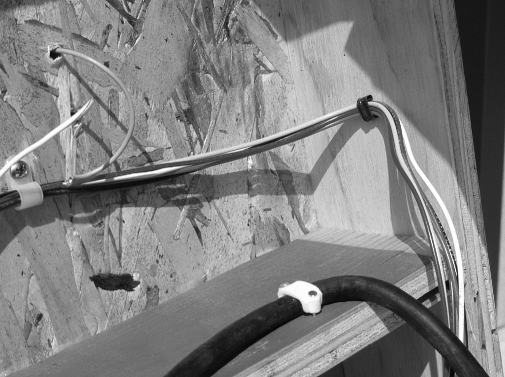
Wiring on the module.
Several members created sections of track controlled by on/off switches located on the back lower left end side of their module. We recently suggested that every member try to include controlled sections of track with switches located in the same general area on their modules so we could stop trains on either of the main lines on any module. That will give us more control and eliminate any guess work of the location of the on/off switches.
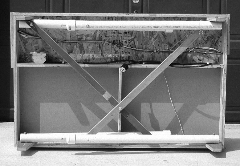
Bottom of the ready-to-transport HO scale module.
Our four corner units incorporate 27½” and 30″ radius curves. They’re large enough to operate Northern type brass locomotives without shorting out and long passenger cars look great rounding the outer curve. Also, engines or cars with large overhanging edges do not rub against one another.
Our current setup consists of 12 member-owned straight units and four Club-owned corner pieces. We also built two “bridge” units that are four feet long and only 1 foot deep. They allow us to fill in an odd space when-ever we have an uneven number of normal sized modules. When we have an even number, we merely add the bridges to create a longer mainline.
Each module is equipped with a painted blue sky and cloud covered Masonite backboard. It’s attached with screws, “C” clamps or bolts, depending on the owners choice. Even the bridges have their own backdrops.

HO scale module showing backdrop.
The group recently completed an inner staging yard system that uses a six foot module with switches and crossings, allowing us to set up and remove new train consists outside of public view. It, of course, is offset by another six foot unit at the other end.
The total cost of a basic 30″ x 4′ module, including track, but not the switches or turnouts was $43. We were able to buy our wire, mounting hardware and electrical connectors from large distributors who gave us quantity discounts.
The group is able to move into a show site and be set up and running in about an hour and a half. Everyone knows what needs to be done and the display just seems to fall together. After everything is running correctly, we hide the clutter that develops under the layout by wrapping the display with a light tan burlap material. We attach it into the edge grain of the plywood with push pins, leaving only the painted front edge of the modules showing.
We’ve had a lot of fun with the modular display. New members have been recruited from the viewers and the display gives all us a chance to visit with the public and tell them about the hobby. I hope some of the things we have done can be applied to your modular efforts because they sure have made our display efforts less stressful.


