text and photos by Richard E. Napper, MMR
Originally published in the Summer 1996 Caboose Kibitzer
I have always wanted to have prototypical signals on my layout, but the cost of prefabricated signals is rather high, so I thought there should be a way to make your own at home for a fraction of the cost. Although the cost of the materials is small, you can produce a very believable searchlight signal with these simple parts.
You will need the following items:
- #10 S.A.E. steel-zinc washers
- T-1 size bi-color LED (red/green with two leads)
- 7/32″ O.D. brass tubing
- 5/32″ O.D. brass tubing
- 1/8″ O.D. brass tubing
- #36 gauge telephone wire
- .080″ styrene plastic
- .020″ styrene plastic
- Walthers signal ladder stock
- Tenax-7R styrene glue
- Bob Smith’s purple super glue
- 180 ohm, 1/4-watt resistors
Cut a base for your signal out of .080″ styrene, say 6’x8′ HO scale. Cut and stack 4’x6′ pieces until they are about 6′ high. Top this stack with one 3′ square piece of .080″ styrene which you have beveled all four edges. Cement your stack to the base, making sure to center the stack on the base. You may wish to sand or otherwise smooth the stack of styrene before gluing to the base. Cut a door from .020″ styrene to 4’x5′ and glue to the side of the signal facing away from the track. Add small pieces of styrene for hinges, and a piece of .015″ brass wire for a door latch.
Drill a hole through the entire stack, centered in the top of the 3′ square piece on top of the stack. Use a #22 drill and go slowly as to not melt the styrene.
Solder the 5/32″ and 1/8″ brass tubes together. The 1/8″ tube will slide inside the larger tube. Cut the smaller tube to 20′ in HO scale, and the larger type to any length that will allow it to fit through the base stack and protrude out the bottom far enough to penetrate your benchwork. You may fabricate a small styrene point to add to the top of the 20′ pole. Install the tubing into the base so that just a small amount of the larger tube shows about the styrene base, making it look like a base ring for the mast. Superglue the brass tubing to the base.
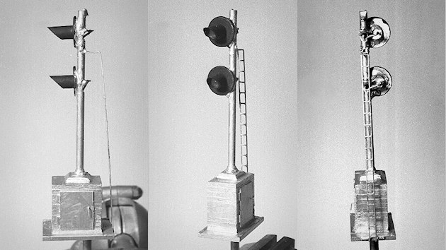
Cut a piece of 7/32″ brass tubing at an angle of about 30 to 45 degrees, and about 1/4″ long. Fit the square-cut end of the tube into the center of the #10 washer. You may have to file the circumference of the LED down just a little, but it should fit inside the tubing and washer, making your signal head. Superglue everything together from the back side of the signal head.
Decide where you want to mount your signal head(s) on the mast, and use a round file to cut a notch in the back side of the mast. Superglue the signal head(s) onto the track side of the mast. Bend one of the LED wire leads so it contacts the mast just above the notch, and solder it to the mast. Run a #36 gauge telephone wire inside the mast to each head, bringing to out at the notch so it may be solder to the other lead of the LED.
At the very bottom of the brass tubing, at the end that will be below the benchwork, solder one more wire as your circuit common for all the signal heads. In series with each wire coming out of the brass tube going to an LED, add a 180 ohm resistor for use with 5 volt TTL signal logic. If you are using 12 volt logic, substitute a 510 ohm resistor.
Add the Walthers signal bridge ladder stock to the back side of the signal mast. Many, but not all, masts have a letter “A” or number attached to the mast, which you may cut from styrene, attach with superglue and letter.
Paint the signal head black, and the mast, ladder and base cabinet silver to finish your new searchlight signal. Reversing voltage polarity will make the signal head light red or green.
Your completed signal is slightly big for exact scale, but it is close enough that you won’t notice it, because the other proportions are correct. You total cost per signal should be about three dollars instead of the twenty dollars or more for prefabricated signals.
Remember the Frisco!


Thanks for the ideas. I’m part of a small club and we need all the help we can get to save money. I’ve tried my first light and it worked well, but looks a little rough. I’m sure I’ll get better as I get more experience.