text and graphics by Richard Schumacher
Originally presented as a clinic at the Long Beach NMRA National Convention
Types of Detection Systems
Two general categories of detection devices exist, point detectors and current (or occupancy) detectors. Point detectors determine that some event has happened at one specific location. Occupancy detectors determine that something is within a block somewhere.
Early model railroad point detectors were triggered by the weight of a train pushing down a special track section that had a built-in switch (Walthers “Trigor” track is of this kind). These require constant adjustment, are easily damaged, and are not very reliable in normal operation (you can’t ballast the track either).
Magnetic point detection uses either a reed switch or Hall Effect sensor to detect the passing of a fairly powerful magnet (usually glued to the bottom of the engine or tender). This method only detects the passing engine.
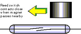
Reed switch detector
This is useful for a diesel horn or steam whistle trigger. I have also used it for display-type layouts which automatically run trains in preprogrammed patterns (as you are really only interested in when a train reaches a specific location to make this work). A streetcar that stops for passengers, or to wait for another to pass, might be typical for most layouts. Such a scheme would use reed switches configured for check-in/check-out logic.
In this circuit, reed switches (with appropriate buffers and pull-up resistors), would be connected to the “reset” and “set” inputs. The relay’s contacts could turn off power to a small track section, stopping the streetcar when the circuit is “set,” and releasing it when “reset.”
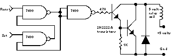
Check-in/check-out reed switch block detector circuit
Reed switches are enclosed in glass tubes that are somewhat fragile. Hall effect sensors are smaller, and solid state, but can require more complex wiring, usually a more powerful magnet, and are picky about the polarity of the magnet (usually the magnet’s “south” pole must be down – make sure you have it the right way before gluing it to the engine). Besides the disadvantage of only detecting the engine, the magnets tend to collect every loose track nail and spike in your train room. In the non-model railroad world (yes, there is such a thing!), magnetic detection is primarily used for home alarm systems to detect open doors or windows.
Photodetectors are the final type of point detectors. These work by something blocking a light source from shining on the photodetector. Many published circuits have used CdS cells (which are light-sensitive resistors), but these are sensitive to changes in room lighting conditions (forget turning off the room lights for “night operations”), and require a light bulb light source which can easily be seen and burn out. A much more practical photodetector setup uses a “matched set” of IR (infrared) LEDs and photo-transistors. Your television remote control uses an IR LED to “talk” with the IR detector in the television set using a complex stream of pulses. IR has the advantages of not being effected by room lighting changes, invisible to the human eye, effective over long distances, and are usually the easiest of the point detection methods to install, adjust, and maintain.
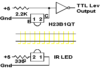
Photodetector block detector circuit
Digi-Key stocks the low cost H23B1QT photo darlington matched pair used in the above circuit. When you get the pair, the black one is the LED and the yellow the photodarlington. One side of each has a “bump” which is the active side.
The above circuit provides “clearance” detection for hidden trackage (“did the train reach a specific point yet?”). The IR LED/detector pair in this example is of the low-cost variety. This specific detector needs the IR LED to be within about 2 inches. The detector is also of clear plastic and detects visible light as well as IR, so the detector needs a short black “hood” or “directional tube” attached to the front (which will point at the IR LED), and all other sides light-proofed (black electrician’s tape works well). You would mount this pair on the sides of the hidden track to detect, slightly below the “beltline” level of the rolling stock.
For IR circuits “out in the open,” I would recommend a more powerful IR source LED, and a detector “blind” to visible light (they have a special “lens” and cost more). IR detectors can sometimes be difficult to work with due to the fact you can’t see the IR light. A hidden track detector can be easily made with a ULN3330Y and a regular (visible light) lamp.
IR photodetectors only work when something is blocking the light path between the IR LED and its sensor. This means positioning the two devices with respect to each other, and what will block the IR light beam (by passing between them), is extremely important. Usually you want to detect a passing train. To make sure all the cars are detected, you need to position the IR LED low, pointing up towards the detector mounted higher on the opposite side of the track. The light path needs to be at an angle or diagonal to the track as well. In this way, both short (flatcars) and tall cars will be detected, and the gaps between the cars will not cause the detector to flash on and off.
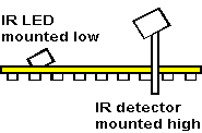
Installation detail for photodetector detection
Good applications for IR point detectors include crossing gates, clearance indicators (for hidden track), and check-in/check-out automation (instead of reed switches). Another use is engine detection with command control systems, in which case the IR LED is mounted on the engine pointing downward, and the sensor is mounted between the rails point up. A constantly lit LED will trigger the detector as it passes (like a reed switch), but some advanced electronics could be used to also transmit (like your remote control) the engine’s receiver number as it passes, so you would know what engine passed that point.
Two other special IR point detection options exist. One is detection by reflectance. In this case, a special detector (that has both the LED and sensor in one package) is mounted between the rails pointing up. Engines and cars have reflective material stuck to their bottoms. The reflective detectors are triggered by the passing of the reflective material. This reduces the alignment complexities required for IR detector pairs, but at added cost.
The other is mounting a laser bar code reader between the rails pointing up. Bar code labels are fastened to the bottom of the rolling stock, and your computer can read the car numbers as they pass by (maybe even throw the turnouts automatically in that working hump yard to select the correct track for each car too!). This uses technology similar to the scanners at supermarkets. As you would guess, you can easily sink lots of money into this option although it’s actually very simple as the bar code readers pretend to be “normal typing” at a computer keyboard to your computer (a decoder box connects between the real keyboard and the computer). Maybe we’ll call this our “ultimate” point detector.
Most modelers want to add detection circuits to operate trackside signals and CTC or control panel occupancy indicators. For these applications, you need to detect rolling stock anywhere in the block, not just those cars luckily sitting at a point detector (photocells or IR devices). Like the real railroads, a system that detects when a train completes a circuit across the rails is required. The most common systems to accomplish this for model railroads are current-based detectors.
Current Detectors
Current detectors measure the flow of current between the rails caused when a powered engine, lighted car or a car equipped with a current path (resistor) is in the block. When a block is empty, there is no current flow to detect. Since this detector measures current flowing between the rails at any point within the block, this method provides detection for the entire block.
The first effective current detector was Linn Wescott’s “Twin-T” (1958!). However, better detectors can now be made using operational amplifier (OpAmp) integrated circuits (ICs). The most versatile current detectors use OpAmps in their design, one of the best examples being Bruce Chubb’s “Optimized Detector” (August 1985 Model Railroader). OpAmp detectors unfortunately have the disadvantage of fairly large part counts (23 in Bruce’s design, even more in other designs), enough to require expensive printed circuit boards for reliable assembly. Many also have features beyond that needed for simple detection and signaling.
Easier to assemble current detectors can be designed using a variation on the engine “constant lighting” trick. Traditional “constant lighting” works by the voltage drop (1.4 volts) across two series diodes providing sufficient current to power a light blub. A motor running at 0.1 amp provides enough power through the “constant lighting” diodes to light a low current bulb. Low current motors cause problems with this “constant lighting” technique because a good “can” motor running at 0.03 amp only provides about half the power a typical 60 ma low current lamp needs to light at 1.4 volts.
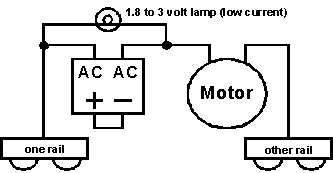
Engine constant lighting
Engine constant lighting
100 PIV, 1 amp bridge Digi-Key DB102-ND $.66 ea or Radio Shack 276-1161 $.99 ea (heavier bridge required for current pig motors)
Warning! All prices listed in this article are from 1996 when this clinic was presented at the Long Beach NMRA National Convention. Please look up current prices before ordering parts now.
You can simplify the construction of an engine “constant lighting” circuit by strangely wiring a bridge rectifier (yes, this is a one part plus bulb “constant lighting” circuit for engines with motors drawing moderate amounts of current). The bridge rectifier takes the full current load through the motor, so the rating of the bridge has to be higher than the motor’s peak current draw.
The engine “constant lighting” circuit “detects” current flowing through the motor of the engine and lights the headlight as the result. Now, if the circuit was connected to the block wiring instead of in the engine, it would still “detect,” but the “lamp” could be on a control panel instead.
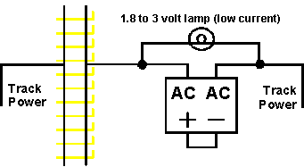
Constant lighting style “block detector”
Constant lighting style “block detector”
100 PIV, 2 amp bridge Digi-Key BR81D-ND $.98 ea or Radio Shack 276-1171 $1.59 ea
Unfortunately, we still have the major problems that (a) it won’t light the lamp with a very low current can motor engine, (b) it won’t light when running power is not attached to the block, and (c) when it does work, it will only light the one bulb (and cannot control other devices, like trackside signals). When using this design, note that the bridge rectifier has to handle the total current draw for all the motors and lighted cars in the block and must be rated above the total possible maximum load.
But there’s a way around this too. An LED (light emitting diode, which can be thought of as a “solid-state lamp”) needs much lower wattage to light than a bulb, in fact it will light in the above circuit with even the lowest current “can” motor engines. So if we replace the bulb with an LED, we now have a simple detector that solves the low current motor problem. However, the other two problems still remain (circuit only works when there is track power applied, and we only have the one LED as an indicator), and we added a new problem – one LED will only “detect” trains running in one direction, since LEDs are sensitive to polarity.
We can solve the LED polarity problem by using two LEDs wired back to back but with opposite polarity. This adds an unexpected benefit, the two LED indicators will also show train direction, as one with light for each direction. A very low value current-limiting resistor (5-15 ohms) may be required in series with the LED if you select an extremely low current LED for your indicator.
Some may suggest using a bi-color red/green LED (which is actually two LEDs in one package, wired back to back with opposite polarity) for the indicator . Unfortunately, most bi-color LEDs require more current to light than provided by this circuit.
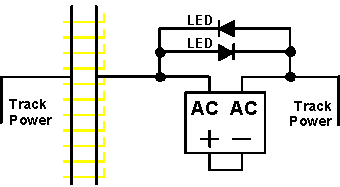
Constant lighting style LED “block detector”
Constant lighting style LED “block detector”
100 PIV, 2 amp bridge: Digi-Key BR81D-ND $.98 ea or Radio Shack 276-1171 $1.59 ea Low current LED: Digi-Key P363-ND $1.68/10
Although this circuit works well for instances when you only need a LED panel indicator showing if a running train is in a track section (such as a helix or tunnel broken into a number of sections so the panel indicators can show the train’s progress), it would be much better if the “detector” could control other devices, like trackside signals, in addition to the panel LED.
Replacing the LED with an “AC” input optoisolator (which also has two LEDs wired back to back inside so it will “detect” regardless of track polarity), you can use the sensitive buffered and amplified output from the optoisolator to operate panel LEDs, signal circuits, and other devices. We have now created a basic detector.
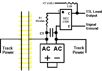
Basic block detector
Basic block detector
| D1 | 100 PIV, 2 amp bridge rectifier Digi-Key BR81D-ND or Radio Shack 276-1171 |
$.98 ea |
| C1 | 0.1 mfd metal poly capacitor Digi-Key EF1104-ND |
$.26 ea |
| R1 | 33 ohm ¼-watt resistor Digi-Key 33QBK-ND ($3.89/200) or Radio Shack 271-1104 |
$.02 ea |
| R2 | 2.2K ¼-watt resistor Digi-Key 2.2KQBK-ND ($3.89/200) or Radio Shack 271-1325 |
$.02 ea |
| IC1 | NEC 2506-1 optoisolator Digi-Key PS2506-1NEC-ND |
$.83 ea |
The 33 ohm resistor R1 is needed to protect the optoisolator’s internal LEDs when a high current draw engine is used, as it limits the current through the optoisolator to a safe level (this one “self destructs” at 80 ma). The bridge rectifier D1 takes the full current of the motor and any lighted cars, so it needs to be at least 2 amps (larger if you run big-time current-pig engines or “SP-style” multi-unit lashups). This circuit is not as sensitive as an OpAmp based detector, but does have the combined advantages of simplicity and low cost.
You could use this basic design, and for some applications (such as control panel indicators) it will work just fine. However, model railroads have an ugly problem lurking at the very foundation of their being to disturb the operation of engines and detectors – dirty track.
Dirty track, dirty wheels, and other track pickup problems will cause the output of the basic detector to flicker, slightly annoying on control panels, but completely unacceptable for signals (I prefer flashing red and green lights only on my Christmas trees). What we need to add to the circuit is a turn-off delay, eliminating the flicker of dirty track while also simulating the turn-off delay of the large mechanical relays used in prototype signals.
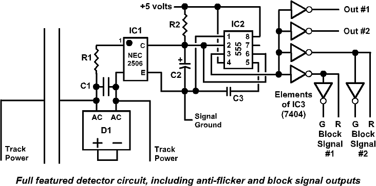
Full featured detector circuit diagram
| D1 | 100 PIV, 2 amp bridge Digi-Key BR81D-ND or 4-amp version, KBL01-ND or Radio Shack 276-1171 |
$.98 ea $1.90 ea $1.59 ea |
| C1 | 0.1 mfd metal poly capacitor Digi-Key EF1104-ND Jameco 93921 (MY.1/250) |
$.27 ea $.23 ea |
| C2 | 10 mfd electrolytic capacitor Digi-Key P6616-ND Jameco 29891 (R10/50) or Radio Shack 272-1025 |
$.17 ea $.09 ea $.59 ea |
| C3 | 0.01 mfd disc capacitor Digi-Key P4300-ND ($.63/10) Jameco 15229 (DC.01) ($.60/10) or Radio Shack 272-131 ($.59/2) |
$.06 ea $.06 ea $.30 ea |
| C4 | 10 mfd tantalum capacitor Digi-Key P2013-ND Jameco 94060 (TM10/16) or Radio Shack 272-1436 |
$.35 ea $.49 ea $.79 ea |
| R1 | 33 ohm ¼-watt resistor Digi-Key 33QBK-ND ($3.89/200) or Radio Shack 271-1104 ($.49/5) |
$.02 ea $.10 ea |
| R2 | 120K ¼-watt resistor Digi-Key 120KQBK ($3.89/200) or Radio Shack 271-1311 ($.49/5) |
$.02 ea $.10 ea |
| R3 | 2.2K ½-watt resistor Digi-Key 2.2H-ND ($3.96/200) Jameco 107609 ($1.29/100) Radio Shack 271-1121 ($.49/5) |
$.02 ea $.01 ea $.10 ea |
| IC1 | NEC 2506-1 optoisolator Digi-Key PS2506-1NEC-ND |
$.96 ea |
| IC2 | 555 timer Digi-Key LM555CN-ND Jameco 27422 (NE555V) or Radio Shack 276-1723 |
$.88 ea $.35 ea $1.19 ea |
| IC3 | 7404 hex inverter Digi-Key DM7404N-ND Jameco 49040 (7404) or Radio Shack 276-1805 |
$.82 ea $.39 ea $.99 ea |
The duration of the turn-off delay is controlled by the values of resistor R2 and capacitor C2. The charge in capacitor C2 is immediately dumped through the optoisolator IC1 when something is detected in the block. This quickly changes the “detected” outputs to a logic low state. As long as something is detected in the block, C2 cannot recharge.
When the block becomes empty, C2 is slowly recharged through R2. IC2 monitors the charge on C2 and switches the output back to a logic high state when the charge reaches the threshold level. Dirty track “flickers” the optoisolator IC1 on and off, but doesn’t give C2 sufficient time to recharge. This eliminates “flicker” from the output. The 10 mfd value of C2 gives about a one second delay. A larger value capacitor will produce a longer delay, about two seconds for 22 mfd and four seconds for 47 mfd.
Alternate values for capacitor C2 with Digi-Key part numbers and prices:
| C2 | 10 mfd electrolytic, P6616-ND |
$.17 ea |
| C2 | 22 mfd electrolytic, P6606-ND |
$.17 ea |
| C2 | 47 mfd electrolytic, P6608-ND |
$.22 ea |
One element from a 7404 hex inverter chip is required to make the output logic for this “anti-flicker” detector the same as the original basic circuit logic (low=detect and high=empty block). This means that 5/6 of the 7404 chip is unused. One possible option for the rest of the 7404 elements would be to share them with five other detectors. A better approch is to use the rest of the 7404 to add outputs to the “anti-flicker” detector so that it can directly control basic LED block signals.
The final enhanced detector has six outputs. Two outputs (Out #1 – Out #2) either directly control a panel LED or are inputs to some other device (like a computer or a highway crossing flasher module). Two pairs of outputs were also added to directly control two 2-color LED block signals, or work as inputs to an interlocking or 3-color signal controller. Each of these outputs can directly power an LED.
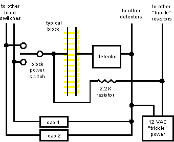
Finally, to detect rolling stock when the engine power is not applied (and you are not using a command control system which has power on the rails all the time), you must provide a detection “trickle” power connection for each block. Engines and lighted cars will automatically be detected, as well as cars with resistor-equipped axles.
A 1/8-watt resistor may be added to one axle of each car so it will be detected. You can install a traditional resistor by its wires, force fit into small holes drilled into metal wheelsets (like Kadee or Jay-Bee) near the axle. You can also “superglue” a surface-mount resistor (such as Digi-Key P2.2KEMG, $6.48/200) on a non-conducting axle, and complete the circuit to the metal wheels with conductive epoxy or paint. Wheelsets with built-in resistance are also commercially available. With conventional throttles, 2.2K works well.
The easiest way to start out is to light every passenger car and caboose. That way the front (engine) and end of each train will be detected.
Overall wiring for DC throttles
The “trickle” resistor is “R3” on the main parts list. Only the two “track power” detector connections are shown, the “+5 volts” and “signal ground” wires that go to each detector are not shown.
The “trickle” power supply needs to be completely separate from the throttles (you cannot use one of the AC outputs on one of the throttles), a “plug in the wall” 12 volt AC transformer, such as a Radio Shack 273-1610A, works well. Using AC avoids detection errors at specific low throttle speed settings.
When actually wiring for normal throttles, physically locate the “trickle” resistors on the block power toggle or rotary switch on the control panel (one end of the resistor connects on the block switch where the wire to the block is also connected). This makes the wiring a lot easier.
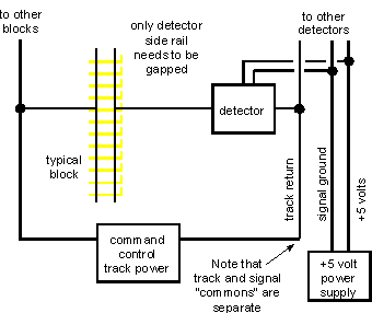
Using conventional or transistor throttles requires both rails to be gapped. The rail on the block switch side is gapped to define the electrical control blocks. The detector side rail is gapped for the signal blocks. The gaps do not have to be across from each other (the control and signal blocks can start at different points).
Since command control, including all the new DCC systems, has power on the rails at all times, track wiring is very simple since the command control itself provides the detection “trickle.” You still need to add insulating gaps for your signal blocks on the detector rail, but you don’t need the additional “trickle” power supply or “trickle” 2.2K resistors. This detector should work with all the common command control systems, and it has been tested with DCC and Onboard systems. For DCC systems you need to remove capacitor C1 from the circuit.
Because of the high currents supplied by command control systems, it is strongly recommended that a 4-amp bridge be substituted for the 2-amp part in all the above circuits to prevent damage to the detectors when the track is shorted. The 4-amp bridge is Digi-Key part KBL01-ND, $1.53 ea.
With command control, gaps only need to be added to define the detection blocks on the “detector” side of the track. The other side only needs gaps as required for turnouts or crossings.
Note that unlike most other current detection circuits, a big advantage of this detector is that the signal delay and logic circuits are completely electrically separate from the track circuit. This complete electrical isolation prevents problems and interactions between the command control system and the detection logic. This also vastly simplifies wiring of reversing sections. You can use off-the-shelf reversing section control circuits for command control while still having complete block detection of the reversing section.
Overall wiring for command control
No “trickle” circuit is required making the wiring very simple. The “+5 volts” and “signal ground” wires that go to each detector are shown here.
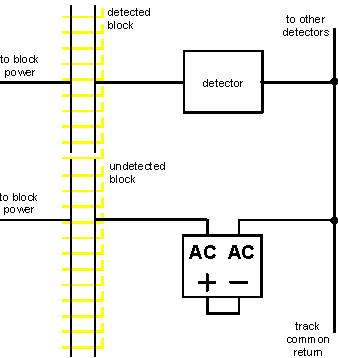
Wiring for undetected blocks or sidings
Use the same bridge rectifier used in the detector.
The detector reduces the track voltage by 1.4 volts due to the bridge rectifier. This can actually be an improvement with conventional throttles, reducing the (usually too high) top speed of engines. It didn’t seem to effect the operation of the command control systems we checked (including the ability to run a non-receiver engine on a DCC layout). Most command control systems have a voltage adjustment, the best situation would be to adjust the voltage up the 1.4 volts to return it to its original at-track level.
However, you need to make sure that undetected areas on the layout (such as yards and sidings) also have the same voltage drop, so engines don’t suddenly jerk or change speed when moving between detected and undetected trackage. The easiest way to accomplish this is to include a same-amperage bridge (with the plus and minus wired connected together just like the detector circuit) from the undetected track to the track common.
Most industry sidings off the mainline will need to be gapped on the “signal” rail and require this type of wiring, especially if you are using turnouts (such as Atlas) that simultaneously power all routes. Otherwise, rolling stock on the siding will be detected.
The detector circuit and control panel and signal LEDs also require a stable, regulated 5 volt power supply. Close does not work here, you need to use a power supply designed to provide the exact 5 volts that the TTL-type parts used in my detector and signal control circuits require. Such a supply may be purchased or easily assembled from parts. Although computer power supplies have a 5 volt output, please note that they do not work right unless the power supply has a fairly large load (like dozens of detectors, signal controllers and LEDs) connected. If you do have a large load, computer power supplies are the most cost effective approach.
This 5 volt power supply circuit may be assembled to control detectors and signals on a small layout. Larger, or additional, 5 volt supplies will be required if you install lots of detectors, signal controllers and LEDs.
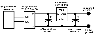
Basic +5 volt power supply
| D1 | 100 PIV, 1.5 amp bridge rectifier Digi-Key BR81D-ND or Radio Shack 276-1152 |
$.98 ea or $1.19 ea |
| C1 | 470 mfd electrolytic capacitor Digi-Key P6657-ND or Radio Shack 272-1030 |
$1.40 ea or $.99 ea |
| C2 | 10 mfd tantlum capacitor Digi-Key P2038-ND or Radio Shack 272-1436 |
$.48 ea or $.79 ea |
| TTR | 5 volt TTR regulator Digi-Key AN7805-ND or Radio Shack 276-1770 |
$.67 ea or $1.19 ea |
| TR1 | “Plug in wall” 9V transformer Radio Shack 273-1656 |
$12.99 ea |
The 5-volt supply has two outputs called “+5” and “signal ground.” The “signal ground” is the common return for the electronics on detectors and signal control circuits. It is not to be confused with the “track common wire” which provides a similar function for track power. The “track common” and the “signal ground” must be connected together, but only at one location. They must be kept apart everywhere else. This avoids logic problems with the electronic circuits caused by the resistance of wire runs. The “+5” and “signal ground” are best run together as a pair of wires under the layout (and use good wire, such as 16 or 18 gauge stranded copper – “speaker” cable works quite well).
Always be extremely careful when connecting power to the detector and other boards with integrated circuits (ICs). If you connect the power the wrong way, you will likely destroy the ICs. Check twice before powering up!
The detector may be assembled on either a general purpose IC PC board, such as Radio Shack 276-150A, or with a custom-made printed circuit board. Project-specific custom printed circuit boards always add greatly to the cost of the project, even if “home made.”
The easiest way to make a disaster out of an electronics assembly project is to use the wrong soldering iron and solder. To assemble a circuit like the detector, you need a 15-watt soldering iron with an iron-clad tip. A starter iron would be the Radio Shack 64-2055 dual-wattage iron with the 64-2058 tip. Iron-clad tips are cleaned by rubbing, when hot, on a dampened sponge. Never file or sand an iron-clad tip. This iron is especially handy for modelers, since the 30-watt setting works well when soldering wire to rails. A better Radio Shack iron can be assembled from parts: 64-2080 handle, 64-2081 23-watt element, and 64-2089 tips.
You also need the correct solder. Very thin, rosin core solder is the best for electronics projects, especially when soldering ICs. The 60/40 .032″ solder from Radio Shack (64-005 or 64-009) is about the right size and works well.
Assembly hints: Parts are inserted on the side opposite the copper pads. Drawings usually show the parts side of the board. You will want to insert the ICs first. Bend the leads (wires) over on the copper side, flat against the copper pads. Trim the excess wire away. The trimmed leads work well for some of the wire jumpers that may be required on the parts side of the board. Be very careful that you do not short across adjacent pads. Use solid wire to make jumpers, or purchase zero-ohm resistors to use as jumpers (Digi-Key 0.0QBK-ND, $4.93/200).
Don’t solder all the pins on the ICs one after the other in a row – you are more likely to overheat the ICs. Instead, solder in a more random pattern.
Assembly Instructions
One of the major advantages of this circuit is that it can be assembled without the need for a relatively expensive custom printed circuit board.
A number of modelers who have attended this clinic or read my original article in the RPO have come to me and said, “Sounds good, I would like to try it – but I’m not sure how to actually build a circuit from those squiggly lines.” This section shows how to assemble the full-feature detector on a hobbyist circuit board available from Radio Shack.
Click here for Part 2: Assembly Instructions
Warning! All prices listed in this article are from 1996 when this clinic was presented at the Long Beach NMRA National Convention. Please look up current prices before ordering parts now.


Richard, for hidden staging tracks, I can imagine mounting several directional light sources above the tracks pointing down, and photodetectors between the rails pointing up. When a car covers the detector, a signal is generated. I suppose this would also work in lighted areas with IR LEDs. Has this ever been tried? For hidden staging tracks, I’d like a detector at each turnout clearance point and one at the center, to be sure that the end turnouts are cleared. Also – how about a “manual” system consisting of a camera showing the tracks, with the signal transmitted continuously to a screen – perhaps an iPad. Thanks.
Both of your approaches have been used by many modelers. A number of IR detectors and circuits are available, and the key to making them work is to control other light sources and shadows that may change the sensitivity of the detection. Baby monitors and household security systems are the least expensive options for a video-based system.
is the diagram for “Basic Block Detector” correct?
https://www.gatewaynmra.org/wp-content/uploads/1997/04/detector-08.gif
https://www.gatewaynmra.org/1997/easy-block-detection-2-color-signals-detection-systems-circuits/
if don’t understand why there is a capacitor across the bridge. My understand is that the AC terminals of the bridge should be reversing polarity with each DCC cycle.
should the capacitor be across the output of the NEC2506, between the 2.5k resistor and ground.
This article was written in the DC control era. The capacitor is there for DC layouts only (to work with an AC bias) and would need to be removed for DCC layouts. Commercially available transformer-based current detectors would be more sensitive for DCC layouts.