text and graphics by Richard Schumacher
Originally presented as a clinic at the Long Beach NMRA National Convention
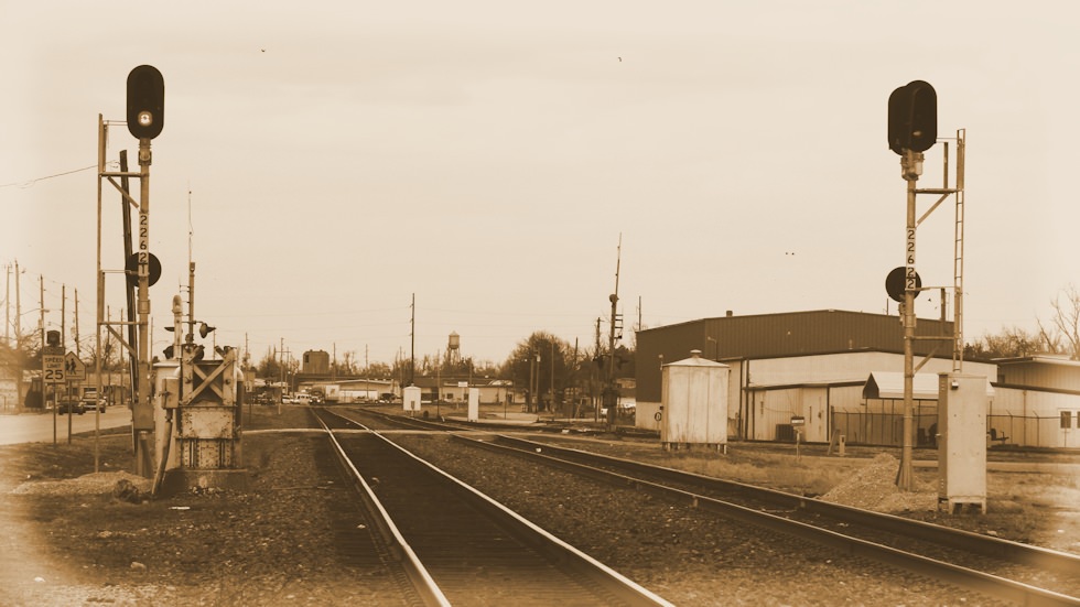
Railroad Signals
Railroads use two types of signals, block and interlocking. Block signals space trains by warning of trains or cars on the track ahead. Interlocking signals control the movement of trains through complex trackwork (turnouts, passing sidings, crossings, crossovers, junctions, or drawbridges).
Real railroads have two types of stop indications: absolute and permissive. Trains must stop at an absolute stop indication, but may cautiously proceed past a permissive stop. Permissive block signals are always marked, typically with a number plate, the letter “P” (permissive), or the letter “G” (grade). MoPac put a number plate on all signals, and marked the absolute ones with an “A” (just to be different most likely). Interlocking signals are always absolute. Since most interlocking signals have multiple heads, they are easily identified. Like the real railroads, if you ever need a single-headed interlocking signal, make sure to mark it “A” so there is no question it is absolute.
Long lengths of track are protected by block signals with two heads displaying “home” and “distant” indications. Two-headed block signals have the heads staggered to avoid confusing them with interlocking signals. Model railroads tend to have interlockings spaced so close that you cannot use two-headed block signals.
Dwarf signals are used for minor trackage within interlockings, as starting signals in passenger terminals, and to signal little-used sidings.
Battery power is conserved by real railroads with the use of approach lighting, where the signal is off until a train approaches it. For model railroads, approach lighting usually reduces the visual impact and effectiveness of the signals.
Model railroad signals typically provide protection against (a) running into an occupied block and (b) running through an improperly aligned turnout. Most stop indications on model railroads must be treated as absolute due to the short distances between interlockings. If all model signals are considered absolute, the number of signal heads and amount of wiring may be reduced by consolidating the function of some block and interlocking signals.
Two color signal indications:
| Green | Green over Red | Clear: proceed on primary route |
| Red | Red over Red | Stop: (what part of “stop” don’t you understand?) |
| Red over Green | Medium Clear: proceed at medium speed on diverging route |
Most model railroads can be signaled using three types of signals: a one-headed block signal, a two-headed interlocking signal, and a one-headed dwarf signal (for yard and miscellaneous trackage). Two-color signals are the easiest to wire, and usually look just as nice and impressive as three-color signals.
Model Railroad Signals
Color light (one lamp per color, arranged in a vertical line with red at the bottom), Type “G” (one lamp per color, arranged as a triangle with red at the bottom), and searchlight (a single lense which changes color) signals are the easiest and most inexpensive to model. Fortunately, they are also the most popular types with real railroads too.
If you decide to model color light signals, you need to decide if you prefer the scale look, non-fading color, and prototypical directionality provided by LEDs, or you want to light up the rails with light bulbs. There is no question that grain-of-wheat (GOW) miniature bulb signals are impressively bright for visitors, but they are much more expensive to install than LED signals because the circuits have more parts and since the bulbs get warm, you must use brass or cast metal signals instead of plastic to preventing melting.
If you decide to use GOW light bulb color light signals, NJ International makes beautiful brass units. Walthers GOW dwarf signals make a nice companion.
If you are modeling searchlight signals the choice is easy, you use a bi-color LED as all the other methods of doing searchlight signals are too complex. Bi-color LEDs actually have two LEDs in one unit, a red and a green.
The best LED signals are made by Oregon Rail Supply. They sell plastic heads to make your own signals, complete color-light signal kits with LEDs, and a really nice cantilevered signal bridge in plastic (which is wonderful, since most model railroads don’t have the space to fit normal signals in many interlockings). [2006 Update: Atlas has released beautiful, completely assembled, Type “G” signals with built-in LEDs].
So You Want to Install Signals …
You need: a TTL-level detector for each signaled block, a switch motor with one set of contacts (SPDT) for each interlocked turnout, and a signal circuit for each signal. The 2-color signal circuit is built into the detector in the first part of this handout. An interlocking controller circuit is needed for each turnout. For 2-color signal systems, this interlocking controller only uses two 50¢ parts.
Some basic knowledge of TTL ICs may be helpful when assembling circuits. Don Lancaster’s TTL Cookbook is a good reference source.
TTL ICs require a regulated +5 volt power supply (see diagram on part 1). They are logic devices: inputs and outputs are either “low” (think “connected” to the system ground) or “high” (think “connected” to +5). There is no “in-between” value or state.
There are many kinds of TTL ICs, these circuits use the “generic” common variety. The ICs used here have either 14 or 16 pins. Each pin is identified by number. Pin one is indicated by a small dimple, or notch out of the end of the package. Pins are identified while look at the package from the top side (the pin points “go down”).
Numbering pattern for 14 and 16 pin DIP ICs (integrated circuit chips)
The circuits to drive GOW bulbs use a special ULN2003A driver IC (easily available from Jameco Electronics). The GOWs could also be driven with resistors and 2N2222A transistors, but the ULN2003A method costs less and is simpler to assemble.
Transistor driver circuit for GOW bulb
These circuits use very simple TTL ICs, they are so simple that multiple gates (logic elements) fit into a single package. The 7400 IC has four copies of the gate circuit in each package (that’s why it’s called a quad NAND gate). The 7404 IC has six copies. And the UPA2003C has drivers for seven bulbs.
In the circuits, leftover gates are ignored. For reliability, unused inputs are connected to +5. Unused outputs are not connected to anything. Ceramic disc capacitors are added between +5 and ground to decrease electronic noise that may cause the circuit to flicker (these are called despiking capacitors). Any value from .01 to .1 mfd. will work fine. Disc capacitors don’t have any polarity to worry about. If you have major problems, try connecting a 10 mfd tantalum capacitor where the +5 line leaves the circuit board (you need to connect the polarity right for this one).
Each TTL IC needs to be connected to +5 and the system ground. The UPA2003A is connected to system ground. These power connections are not normally noted on circuit diagrams, you’re supposed to “know” you have to make them (fun, fun, fun!).
The 7400 is a quad 2-input NAND gate. On any gate, when either input is “low” the output will be “high.” If both inputs are “high” the output is “low.”
7400 is a quad 2-input NAND gate
The 7404 is a hex inverter. On any one inverter, a “low” input makes a “high” output, and a “high” input makes a “low” output.
7404 is a hex inverter
The ULN2003A is a driver. Pin 8 is attached to the system ground. 1 is input for 16. 2 for 15. 3 for 14. 4 for 13. 5 for 12. 6 for 11. 7 for 10. Compare how much easier it is to drive a GOW blub with this IC over the transistor method.
ULN2003A is a driver
Signal Circuits
The basic circuit to drive a 2-color LED color light signal uses 1/2 of one 7400N package (that means you can run two signal heads off one package). The two LEDs are located in the signal head. You also use this same circuit to power the 3-wire version of the bi-color LED for a searchlight signal (the middle wire goes to the +5, and the other two connect to the current-limiting resistors). When either input of this circuit is made “low” the “red” LED lights, when both inputs are “high” the “green” LED lights instead. This same logic is built into the full-featured detector circuit to make the two signal head outputs function.
Basic circuit to drive a 2-color LED color light signal
The GOW version, the 2-color GOW color light signal, works the same way, but requires driver elements from a ULN2003A to power the bulbs. Note that a separate +10VDC supply is used for the bulbs. The “ground” side of the +10VDC power supply is connected to the system ground as well. Be careful not to connect the +10 to a TTL ICs – you’ll have fewer working parts if you do that. You could add the ULN2003A drivers to the signal head outputs of the full-featured detector to drive GOW bulbs (like those in the NJ International signals).
2-color GOW color light signal
I prefer the 3-wire bi-color red-green LEDs over the 2-wire versions. Unfortunately, the 2-wire versions seem to be easier to get in the smaller “T-1” (or 3mm) size more appropriate for installation in a target signal head. The circuit to drive a 2-color LED searchlight signal uses 1/2 of one 7400N package and 1/3 of one 7404N package. The LED is mounted in the signal head. When either input of this circuit is made “low” the “red” LED lights, when both inputs are “high” the “green” LED lights instead. Of course, you have a 50-50 chance of connecting the LED the right way the first time.
Basic circuit for a 2-color LED searchlight signal
Putting it All Together
Connecting block signals is very simple. The output from an occupancy detector is buffered and connected as one of the “inputs” on the signal circuits. When the detector detects, it changes from a “high” output to a “low” one, which triggers any signal circuits to switch to “red.”
Connecting a detector to a signal circuit
Normally, you would connect two signal circuits to each detector – one for each end of the block.
Why are there two inputs on the signal circuits? Because there is something else that can make a signal display a “red” indication – a turnout thrown wrong. We use one set of contacts on the switch motor to provide this indication.
At each “fully” signaled (interlocked) turnout, there will be three signals: two one-head “block” signals at the frog end of the turnout and one two-head “interlocking” and the point end. Actually, the “block” signals are acting as one-head interlocking signals, as they will stay red if the turnout is thrown against them even if the block ahead is clear.
Interlocking signal
The output from the detector for the block at the point end of the turnout is connected as one of the inputs to each of the single-head signals. The detector for block “A” (the straight route) is connected to the top head of the inter-locking signal. The detector for “B” is connected to the bottom head. This provides the expected behavior for occupancy signaling.
The switch motor contacts (SPDT) are connected to the other four (one on each) signal circuit inputs. This adds signal protection for the incorrectly aligned routes.
The circuit diagram for a two-color LED interlocking controller, and the actual wiring for an example situation, are included on the attached pages. This version will work with both rapid action and slow-motion switch motors.
Electronic Project Tips
Use the correct size soldering iron. When assembling small electronic parts, a 15-watt iron will work best. A good “starter” iron is the Radio Shack 64-2055A which can be switched between 15-watt and 30-watt settings. The 30-watt setting on this iron is useful for soldering track feeder wires.
“Tin” the tip of the soldering iron. Heat the iron and apply a thin coating of melted solder. Periodically clean the tip by melting additional solder on the heated tip and wiping it on a damp sponge. Do not file or sand the tip.
User rosin-core solder for all electrical and electronic connections. Radio Shack 64-005 or 64-009 works well for soldering circuits. Don’t over-solder, only apply enough solder to make the connection – you don’t need “blobs.”
Clean the parts before soldering. Most electronic components will be ready to solder, but printed circuit boards may need cleaning. Printed circuit boards come either in plain copper (copper colored) or with a ready-to-solder tin coat (silver colored). The plain copper needs to be cleaned to a bright shiny color to solder well, very light sanding or washing with scrubbing powder will give the desired result. Be very gentle when cleaning printed circuit boards as the copper is very thin.
Always heat the work, not the solder. Hold the tinned iron against the work maximizing the contact area of the tip. After the board, wire or parts have heated for a short moment, feed rosin-core solder to the tip, the solder will flow freely and cover the connection. Only heat as long as necessary, clean parts will always solder instantly.
Warning! All prices listed in this article are from 1996 when this clinic was presented at the Long Beach NMRA National Convention. Please look up current prices before ordering parts now.


